
2D vs. 3D
Some of the 3D codes and/or their conversion scripts seem to have problems with the diagonal elements of the impedance tensors, which causes diagonal phases in the wrong quadrants.
To double check if your 3D code and conversion script provides the correct impedance values, a comparison of the 3D result with a rotated 2D responses is useful.
The sketches below show the 2D model in section view (top) and a plan view of the same model but in 3 dimensions (bottom) - the profile is still perpendicular to the two dyke-like structures of infinite length and the site spacing is the same as for the 2D model, but the orientation of the structure is 45 degrees of North. If you calculate the 2D responses for the model on the top and rotate the coordinate system (COSY) for the resulting impedance tensor by -45 degrees, the rotated impedance should be identical to the 3D responses you get with your 3D forward modeling of the 3D dyke structure (on the bottom).


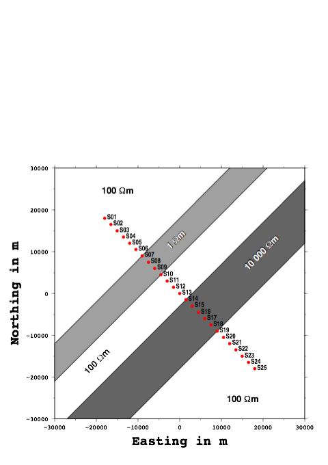
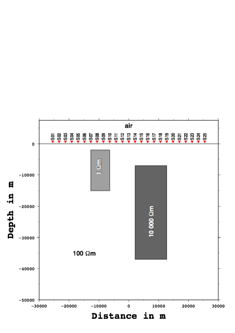
more details about the models
The site spacing is 2.121 km and the profile is perpendicular to the two dyke-like bodies of infinite length, which are embedded in a 100 Ωm halfspace. The edges of body 1 are directly underneath the sites S07 and S10 respectively. The depth extend is from 2 km to 15 km and the resistivity value is 1 Ωm.
The second body (10 000 Ωm) is in a depth of 7 km to 37 km and its edges are directly underneath the sites S14 and S19 respectively.
Calculate the responses for a few decades (roughly 0.01 s - 1000 s) and compare the rotated 2D and the 3D results.
Dublin Institute for Advanced Studies, School of Cosmic Physics, 5 Merrion Square, Dublin 2, Ireland
Tel +353 - 1 - 662 - 1242, Fax +353 - 1 - 443 - 0575, marion@cp.dias.ie
